


Some of this information has appeared previously, but is combined with new concepts in this section as an introduction to bare board QUALITY
The circuit board is the foundation of our electronic products, and is the most critical component affecting long-term reliability. Since most companies depend on manufacturing partners to fabricate the bare boards, we must:
- Select suppliers who are capable of delivering the required level of quality
- Specify the minimum level of acceptability for circuit boards
- Perform checks to ensure that the boards meet the expected reliability
On the other hand, cost is an important issue, and we don't want to impose expensive and unnecessary tests to prove the acceptance criteria. Our goal is to derive the maximum level of confidence for the minimum amount of time and expense.
When determining the level of testing, we should err on the side of caution. One mistake can cause a line-down situation that results in an inability to ship, which can create scheduling and delivery problems throughout the organization. One defective product can damage our reputation and in severe cases, de-value the company brand.
The cost of recalling or scrapping assemblies is always higher than the cost of scrapping bare boards, and the cost of scrapping bare boards is always higher than the cost of proper inspection and process controls along the way. With this in mind, a small investment up front can prevent a catastrophic failure later on.
Circuit Board Requirements
The following three requirements are summarized from "The Printed Circuits Handbook" by Clyde Coombs, and form the foundation for everything that follows:
- The physical form should match the intended design. Dimensions and placement position of interconnect points along with the coating on these interconnection points must facilitate the attachment of components
- The circuit board must provide proper interconnection between components
- The circuit board must provide adequate insulation between interconnection points that should not be connected
These three items should be acceptable and of high quality throughout the expected life of the product. There are many details related to those three requirements, and it is essential that we define what is required for acceptability and quality for circuit board suppliers to ensure that those three requirements are met.
Properly implemented, the quality and acceptance criteria will give all parties a clear picture of what is expected.
IPC
The IPC is an "Association Connecting Electronics Industries" that collects data from member companies and volunteers, and uses that data to create standards, guidelines and requirements.
The value of the IPC is that members can learn from the experiences of other companies, and avoid the cost of duplicating expensive research. It also creates a foundation for everyone to build upon. For example, if the IPC recommends that the plating thickness of hole walls should average .001 inch, all circuit board manufacturers should be able to meet that recommendation consistently, as a minimum.
There are IPC documents available for every phase of electronic development including design, fabrication, assembly, test and documentation.
Here are the publications that are directly related to this tutorial:
| IPC-1710 | Printed Board Manufacturer's Qualification Profile |
| IPC-2221 | Generic Standard on Printed Board Design |
| IPC-2222 | Sectional Standard on Rigid Organic Printed Boards |
| IPC-6011 | Generic Performance Specification for Printed Boards |
| IPC-6012 | Qualification and Performance Specification for Rigid PCBs |
| IPC-A-600 | Acceptability of Printed Boards |
| IPC-9151 | Printed Board Process, Capability, Quality, and Relative Reliability Benchmark |
In addition to these, there are many other IPC documents related to bare board manufacturing on subjects such as materials, drilling, silkscreens, soldermasks, and final finishes. These detailed specifications are crucial for a good design and manufacturing process, but are beyond the scope of this document.
All of these documents are under revision control, but when the document number is used without a revision letter, it is intended to mean "as of the latest revision".

Circuit Board Specification
What is the minimum required to QUOTE a circuit board?
A supplier does not need a complete data package to provide a rough estimate of the cost. Quite often, purchasers are involved in budgetary quoting before the circuit design is even finished. This is the minimum amount of information needed to generate an estimate:
| DIMENSIONAL | What is the size and thickness? |
| ELECTRICAL | How many layers of circuitry? |
| MATERIAL | Standard material or exotic? Required final finish? |
| DRILLING | Approximate number of holes and smallest hole size? |
| COMPLEXITY | What is the smallest trace width and clearance space? |
| TEST | Approximate number of SMT lands? SMT on both sides? |
| DELIVERY | How many boards are needed? How soon do you need them? |
If we called a supplier and said,
"We are designing a 3 x 5 inch two layer FR4 board with 8mil traces and 8mil spaces, about 600 holes, smallest 12mil, no SMT, HASL, the data will be ready on Monday and I need 100 boards by Friday, How much will they cost?"
We could have an answer in minutes, certainly within the hour. Some bare board fabricators will even provide a web-based "instant quote", where you can enter the parameters online and get an estimate without delay.
Circuit board suppliers are willing to provide an estimated quote with the understanding that when the actual order is placed, if there are features that we didn't mention or that we stated incorrectly, they have a right to revise the quote.
What is the minimum required to MANUFACTURE a circuit board?
The answer to this question might be different than you expect.
Using the same example above, if we sent two layers of circuitry in the correct format (Gerber) and a drilling file (and absolutely nothing else) we could get a board from them, ready to use.
Would it work? The answer, in theory, is YES.
Would it work under the conditions we need it to work?
Maybe not...
...but the point is this:
Even without drawings or notes or standards, if we are buying a board from the supplier it must function as a board.
In the case above, the supplier is free to choose whatever materials they want to, and fabricate the boards with whatever tolerances happen to be the default for their processes that day, but the end result would still be a board that must fit the three criteria we listed earlier. It would not have electrical opens where we need connections, or electrical shorts where we need isolation.
Even without supporting documentation, it is expected that a supplier will deliver a board that matches the data provided, or we aren't expected to pay for it.
The Fabrication Drawing
(This was highlighted briefly in the DATA section, but is repeated here)
The fabrication drawing is the master document for manufacturing a circuit board, and has four main purposes:
- It can be used by the purchasing department for quoting purposes
- It communicates critical characteristics to the circuit board manufacturer
- It is a tool for quality inspection, defining acceptance or rejection criteria
- It serves as a record of a product in document control
In this section we are concerned about item number two, but in the section on verification (below), we will be discussing item number three. The other items are self-explanatory.
These are the common specifications found on circuit board fabrication drawings:
- A way to identify the circuit board, part number and revision
- Traceability information about who created/checked/approved the drawing and what design control it belongs to
- A picture of the circuit board with dimensions for the overall size as well as dimensions for any features that are important
- Construction details that describe the layer stack with copper thicknesses, and may include specific laminate details
- A hole chart identifying plated vs. non-plated and sizes
- A method to determine appropriate materials for soldermask, silkscreen and final finish
- Other documents that serve as "attachments" to the drawing
- Any notes that are meant to over-ride the attachments
Regarding the "other documents as attachments" listed above, there are benefits to using separate documents to list the acceptance criteria for bare board acceptability. We don't have to clutter every drawing with a large number of "boilerplate" notes, and by having these as a separate document under revision control, we can change these criteria without having to edit every drawing affected by them.
These documents are generally in the form of internal company specifications or internationally recognized industry standards
Industry Standards
The advantage of using industry standards is they establish a common foundation, they create a "level playing field" that all participants should be able to adhere to as a minimum. It is much easier for everyone to become knowledgeable about a common specification than it is to develop and interpret an endless number of individual company specifications.
The disadvantage of relying on industry standards is that, since they are created by a consensus and a consensus takes time to achieve, they are usually behind the times and represent the lowest common denominator. Many companies are forced to move beyond the standards for various reasons as their design needs advance beyond the scope of the standards available.
Even with disadvantages, if it is possible to adhere to industry standards, many chances for failure will be avoided. For example, if all of the surface mount equipment makers in the world have agreed to recognize a camera target that is a 1mm (.040") round circle, it would be foolish for a board designer to use anything other than a 1mm (.040") circle, and even more foolish for an equipment manufacturer to develop a machine that required anything other than a 1mm (.040") circle.
(Unless, of course, a company found a significant advantage by doing it another way. That's how standards evolve.)
It is up to the customer to specify the level of acceptability.
The criteria for evaluating circuit board quality has been divided up into three categories called "classes". Declaring a circuit board as Class 1, 2 or 3 will automatically identify the minimum set of requirements for acceptability of that product.
| Class 1 | General Electronic Products (consumer products) |
| Class 2 | Dedicated Service Products (uninterrupted service is desired) |
| Class 3 | High Reliability (continuous service is critical) |
Again, it is up to the customer to determine which Class is appropriate for a product. If a toy manufacturer wants circuit boards that meet class 3 requirements and they are willing to pay for the extra level of reliability, that is their decision to make.
IPC-6011 Generic Performance Specification for Printed Boards
This is the root document of a set that covers all types of circuit board technologies (the entire set is labeled IPC-6010).
The first requirement in this document (3.1 General) specifies three things worth repeating here, paraphrased as:
- boards shall meet or exceed all the requirements of the specific class of this specification,
- boards furnished under this specification shall be as specified on the procurement documentation, and
- boards shall be fabricated from design information that includes sufficient coupons to facilitate testing, with the intent that the coupons are as similar as possible to the boards they represent.
Additional coupons may be added at the discretion of the board supplier for product and/or process verification and control, as needed.
IPC-6011 also specifies that (3.3) Verification of compatibility with specifications, master drawings and patterns, and the specific manufacturing facilities and processes used are the responsibility of the supplier. The supplier shall ensure that the end-product board meets the requirements of the printed board procurement documentation.
In addition, IPC-6011 defines the (4.1) Responsibility for inspection. The supplier is responsible for the performance of all inspection requirements. The user reserves the right to perform any of the inspections when deemed necessary to assure that circuit boards and services conform to prescribed requirements.
Other topics address noncompliance, auditing and Statistical Process Control (SPC)
NOTE: It is not my intention to abbreviate or summarize IPC-6011, or any other specification mentioned here. This is only a brief overview for the purpose of introducing you to the relevant specifications, but there is much more information in the documents themselves. Please refer to the actual documents for a more thorough explanation.
IPC-6011 applies by default to all circuit board types, but must be supplemented by a performance specification that contains the requirements for the chosen technology.
Here are the technologies currently in the IPC-6010 set:
| IPC-6012 | Rigid |
| IPC-6013 | Flex |
| IPC-6014 | PCMCIA |
| IPC-6015 | MCM-L |
| IPC-6016 | HDI |
| IPC-6018 | Microwave |
Since the majority of electronic products contain rigid boards, IPC-6012 is the most common specification in documentation packages.
IPC-6012 Qualification and Performance Specification for Rigid Printed BoardsThe first requirement in IPC-6012 (3.1) is that "boards furnished under this specification shall meet or exceed the requirements of IPC-6011 and the specific performance class as required by the procurement documentation."
This requirement allows us to specify only IPC-6012, but get the acceptance criteria of both IPC-6011 and IPC-6012.
Here is a single page of the IPC-6012 Appendix, which is a summary of the requirements specified in the main body of the IPC-6012 document, and a paragraph reference where it can be found. This page is intended to give you a general idea of the type of criteria that it specifies
Again, this is only shown for educational purposes. You must refer to the latest revision of IPC-6012 for the most current set of requirements.
IPC-A-600 Acceptability of Printed Boards
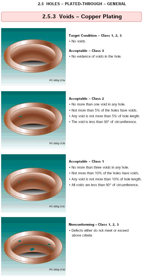
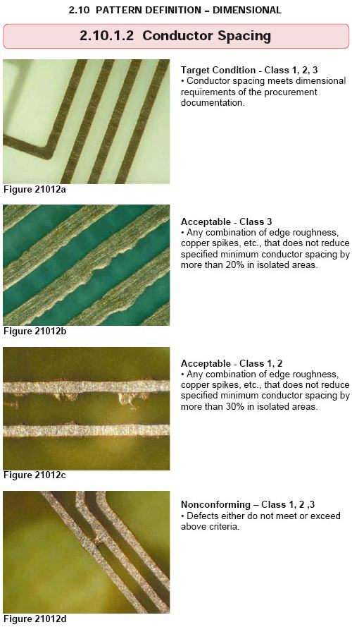
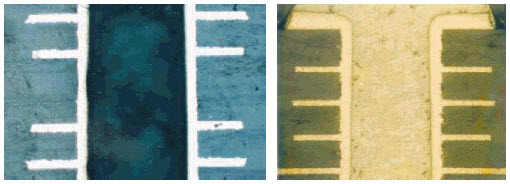
It is sometimes difficult to establish non-conformance criteria from verbal descriptions alone. For this reason, the IPC-A-600 was developed as a visual guide to supplement most of the requirements described in IPC-6012
Most of the illustrations and photographs in IPC-A-600 represent three levels of quality for each specific characteristic; i.e., Target Condition, Acceptable and Nonconforming.
| Target | Depicts the desired condition. May not be necessary to ensure reliability. |
| Acceptable | Indicates that the condition depicted, while not necessarily perfect, will maintain the integrity and reliability of the board in its service environment. |
| Nonconforming | Indicates that the condition depicted may be insufficient to ensure the reliability of the board in its service environment. Considered unacceptable for at least one class of product, but may be acceptable for other classes as specified by the acceptance criteria. |
Characteristics are divided into two general groups:
Externally observable conditions are features or imperfections which can be seen and evaluated on or from the exterior surface of the board
Internally observable conditions are features or imperfections that require microsectioning of the specimen for detection and evaluation
Here is a typical example of visual acceptance criteria, taken from IPC-A-600:
Here is another example from IPC-A-600 using photographs:
Resolving Specification Conflicts
There are various methods for communicating requirements for circuit board acceptability, primarily:
- Purchasing/Procurement Documentation
- The Fabrication Drawing
- Internal Company Specification
- Industry Standards and Requirements
What happens when they don't agree?
A circuit board manufacturer considers the purchaser of the product as the "highest authority" when comparing multiple sources of criteria. Think about it this way; Industry standards provide a "foundation" for everyone to agree on in the absence of any specifics, but a particular company may have decided that its products need "a little extra", and creates a document containing one or more modified requirements for all of its circuit boards. This company-specific document takes precedence over any other generic industry standards or supplier "best practices". Now, let's say for one specific design there needs to be an extra requirement. This extra requirement can be listed on the fabrication drawing in a note, and it will only be applied to that one design. A note like this can over-ride all the other industry and company-specific documents combined. Now let's pretend it is ten years later, the original designer is not avaiable, a purchaser wants to order more boards, but wants something different. Rather than changing the design or the fabrication drawing, the change can be incorporated into the procurement documentation, and that will take the highest precedence.
For example, let's assume that most of the world is using green soldermask, but a company decides it would rather use blue. The company may create a general document that declares the default soldermask color to be blue. On a particular design from the same company, a note on the fabrication drawing calls for a red soldermask. The circuit board will be constructed with a RED soldermask. Now let's assume that a board purchaser wants another order of boards, but would rather have black soldermask. All reference to soldermask color in all other documentation will be ignored, and for that one order, the boards will be fabricated with BLACK soldermask.
In this manner of thinking, customer preferences in the form of a default company specifications, fabrication notes, or procurement instructions take priority over any industry recommendations or supplier "best practices". It is the philosophy that "the customer is always right", provided the customer is willing to accept the consequences.
In some cases a supplier will put a job on hold to verify a discrepancy, but in the end, the customer decides what criteria is appropriate for its products.
Selecting a Circuit Board Supplier
As specified in IPC-6011 (Generic Performance Specification for Printed Boards):
3.6 Qualification Assessment
The supplier shall produce an assessment of their capabilities and sources of verification for a user to evaluate. The user must then review the assessment and determine whether the information and verification provided constitutes an acceptable level of risk.
3.6.1 Self Declaration
The first level of Qualification Assessment is self declaration, Suppliers of printed boards shall assess their manufacturing capability and complete the Printed Board Manufacturers' Qualification Profile found in IPC-1710.
IPC-1710 Printed Board Manufacturers' Qualification Profile
Reviewing the qualification profile is the first step in evaluating a new circuit board supplier. A completed profile contains a supplier's site capability, processing and test equipment, technology specifics, quality program, manufacturing history, company information and data verification sources.
Since circuit board suppliers are being asked for this information more frequently, quite often they will already have the profile completed and ready to provide a copy.
Three sections of the profile are shown on the following pages to give the reader a better idea what it is composed of:
SECTION 2.5 QUALITY DEVELOPMENT

This section is intended to provide overview
information on the quality systems in place
in the manufacturing facility.

Site Capability Snapshot (Check all that apply)

Strategic Plan

[] Functional Steering Committee Formed
[] TQM Plan & Philosophy Established & Published
[] Documented Quality Progress Review
[] Implementation & review of Project Team
   Recommendations
[] TQM Communicated throughout organization
[] Controlled New process Start-up
[] Management Participates in TQM Audits
[] Employee Recognition Program
[] Total TQM Plan/Involvement Customer Training


Employee Involvement

[] Certified Training Available
[] Training of Employee Base
[] TQM Team Trained
[] Design of Experiment Training and Use
[] New Process Implementation Training
[] Support Personnel Training
[] Advanced Statistical Training
[] Quality Functional Deployment
[] Ongoing Improvement Program for Employees


Quality Manual

[] Quality Manual Started
[] Generic Quality Manual for Facility
[] 10% of manufacturing depts. have process
   specifications
[] 25% of manufacturing depts. have process
   specifications
[] 50% of manufacturing depts. have process
   specifications
[] Non-manufacturing Manuals Developed
[] 25% of all departments have quality manuals
[] 50% of all departments have quality manuals
[] All Manufacturing and support depts. have
   controlled quality manual


Instructions

[] Work Instructions Started
[] Quality Instructions Started
[] 10% Work Instructions Completed
[] 10% Quality Instructions Completed
[] 25% Work Instructions Complete&Controlled
[] 25% Quality Instruction Complete&Controlled
[] 50% Work Instruction Complete&Controlled
[] 50% Quality Instruction Complete&Controlled
[] Quality and Work Instructions Completed and
   Controlled


SPC Implementation IPC-PC-90

[] Plan Exists
[] Training Started
[] Process Data Collected & Analyzed
[] All Employees Trained
[] First Process Stable & Capable
[] Several Major Processes Stable & Capable
[] Continued Improvement of Stable Processes
[] Additional Mfg Processes under Control
[] All Processes Under Control


Supplier Programs/Controls

[] Supplier Rating Program
[] Monthly Analysis Program
[] Key Problems Identified
[] Supplier Reviews Performance Data provided
[] TQM Acceptance by suppliers
[] 10% of Suppliers Using SPC
[] 25% of Suppliers Using SPC
[] 50% of Suppliers Using SPC
[] All Key Suppliers using Certified parts program


5.5 PROCESS DOCUMENTATION STATUS

[] Are manufacturing product, process, and
   configuration documents under issue control?
[] Are "preliminary" and "special product"
   specifications controlled?
[] Does the system ensure that the most current
   customer specifications are available to the
   manufacturing personnel?
[] Does the system ensure that the most current
   material specifications are available to the
   procurement function?
[] Are incoming orders reviewed for revisions
   and issue changes?
[] Is conformance to customer specifications
   assured before an order is accepted?
[] Is customer feedback provided when designs
   do not meet manufacturability requirements?
[] Are critical characteristics classified,
   relative to impact on product performance?
[] Are customers informed of changes made to
   products controlled by customer drawings or
   specifications?
[] Is there an effective internal deviation
   control procedure and, are customer requested
   deviations documented and followed?
[] Do new product development procedures exist,
   and are they followed in the design development
   process?


5.6 QUALITY RECORDS

[] Are records of inspection and process control
   maintained and available for review?
[] Are records of equipment and maintenance kept?
[] Is the record and sample retention program
   defined?
[] Are quality data used as a basis for corrective
   action?
[] Are quality data used in reporting performance
   and trends to management?
[] Are quality data used in supporting certifica-
   tions of quality furnished to customers?
[] Is field information used for corrective action?
[] Does a cost of quality measurement system exist?
[] Are customer reported quality problems responded
   to, and resolved in the time period requested?
[] Is quality information on production material
   rejects provided to sub-suppliers with required
   corrective action?
[] Are computers used to collect and analyze
   quality data?
Evaluating a Circuit Board Supplier
A completed profile is only a first step in selecting a new supplier. The profile data should be evaluated to make sure the supplier is capable of manufacturing your products, but it is even more important to arrange a visit to the facility to see the operation first-hand. Representatives must perform an on-site audit of any new facility.
It is important to realize that not all circuit board manufacturers specialize in the same type of board production. The first observation that should be made during a tour of the facility is the general nature of the products being manufactured there. You might see mostly two-layer boards at one facility, mostly high-layer count backplanes at another facility, and another that specializes in high-volume cell phones or motherboards. The marketing brochure may list 30-layer capability with 4mil lines, but if they don't actually manufacture those type of boards on a regular basis, the buyer should be wary of putting an order like that with them.
The purchaser wants to balance cost with quality. You don't want to send a 50-piece order for a simple two-layer board to a huge overseas manufacturer who is busy making millions of boards for cell-phones.Why? Because it will cost too much. The huge manufacturer typically wants huge orders. They typically set up a single design and have it run for weeks at a time. Are they going to be interested in loading up their equipment for a 50 piece order? Only if the price is right. They will only accept that job if we make it worth their time to slow down the big operation. We will get a far better deal by finding a supplier who specializes in small low-volume runs.
Let's take that example of a two-layer board one step further, and think about the difference in process steps from a multi-layer construction. A two-layer board is constructed with a single piece of fiberglass with copper on both sides. The copper is etched away to form the desired circuit pattern, holes are drilled and plated, and that's about all there is to it (except for the coatings soldermask, finish and silkscreen).
In a multi-layer circuit board manufacture, each pair of inner layers is separately etched, then laminated together with the outer layers which need to be etched, and without getting too detailed there are many additional factors in addition to layer registration and final thickness variations. Many operations aren't used in two-layer construction, and many inspection steps aren't necessary. So a smart purchaser will place that order with a vendor who specializes in two-layer boards for a lower price. The point of this example is that it is important to learn the capabilities and the differentiation between various approved vendors, to know how to use them most effectively. In other words, to get the most reliable product for the lowest price.
It is important to understand that some vendors can be approved for low technology products and still be reliable, but not be approved for higher technology design capability.
Many other observations will contribute to the over-all perception of a supplier; the general cleanliness of the facility, the orderly layout of work cells to minimize handling of material, written procedures and good record-keeping, printed metrics posted at various work-sites, etc. Look for good process control and a culture of continuous improvement.
This type of information can't be obtained from a marketing brochure.
For example, if one vendor is using Automated Optical Inspection of inner layers, sorting out any defects and recording the failure rate for process improvement, and another vendor has an army of teenagers doing visual inspection and fixing errors on the fly without recording the frequency of repair, you have a very good idea which vendor should be preferred.
As another example, A casual conversation with the CAM operator may reveal a lot about his role in the organization. One manufacturer may have him doing a complete Design Rule Check on the supplied data, and modifying it with venting, thieving, tear-dropping and compensation to get the highest yield possible, while another merely sends the data out to a third party to generate "master film", using the data "as is". Needless to say, you would prefer the former.
To summarize, it is in your best interest to become familiar with your supplier's processes, visit them personally and determine which type of circuit board designs they are best capable of manufacturing.
For more insight on "Selecting PCB Suppliers", see Appendix 3 of Lee Ritchey's FREE book, "Right The First Time" available HERE
and a funny but sensible quiz written by "The Printed Circuit Girls" and published by PCB007 can be found HERE
Product Verification
There are a few points to be made related to verification before and during the circuit board manufacturing process, but most of the verification activities we are concerned with occur at the end, after the boards are finished. The two worth mentioning are CAM and Process:
Computer Automated Manufacturing (CAM)To start a new circuit board order, the supplier will load the data provided by the customer into their CAM system and generate a netlist, which is the point-to-point connections of all the circuitry in the design. This netlist will be compared to the netlist provided by the customer, to make sure the CAM data matches the design data before starting. If it doesn't match, the job is immediately put "on hold" until the discrepancy is resolved. This is the first step in verifying that the finished product will function as intended.
Require a netlist check on every new circuit board order!
There are many other types of data manipulation that can be performed by the CAM operator to improve the performance and yield. These are desirable but are not part of the requirements or board verification process, and as such will be considered beyond the scope of this document.
Process ChecksThese are developed by the circuit board manufacturer as tools to ensure that the fabrication process is under control. For example, examining hole wall quality before plating, inspecting inner layers for shorts and opens before lamination, checking chemistry levels in plating tanks, etc. These controls are beyond the scope of this document, except to say that they should be available for review on a periodic basis for auditing purposes.
Inspection Lots and Sampling
Circuit boards are manufactured and delivered to the customer in batches, and for purposes of verifying acceptability are referred to as "inspection lots". An inspection lot consists of all the circuit boards fabricated from the same materials, using the same processing procedures and constructions and produced under the same conditions. It is the circuit board manufacturer's responsibility to maintain traceability for all the boards in an inspection lot, along with corresponding test coupons that were separated from the production panels. (Printed Circuits Handbook 51.4).
For some attributes, 100 percent inspection is not necessary or prudent, and a sampling of the boards is allowed to represent the entire inspection lot. Understanding the manufacturing process is critical in forming a sampling group that is representative of the product.
It is important that all inspections be carried out with equipment that is calibrated and traceable to internationally recognized standards (IPC-QL-651)
Methods of Verification
Here are the primary methods used to verify circuit board acceptability:
Visual/Dimensional
Visual inspection is typically done under low magnification (1.75x), but can be increased as necessary to resolve non-conformance issues. The magnification for inspection of dimensional attributes should be sufficient to make an accurate measurement to determine acceptability.
Test Coupons
Test coupons are small patterns of conductors and holes placed along the edges of the fabrication panel, or between individual circuit boards in the fabrication panel. Coupons allow reliability and destructive testing to be performed without having to waste good boards.
The Verification Process
Visual/Dimensional
Measurements should be made to verify critical dimensions and features, and submitted as a First Article Inspection (FAI). This is a sample FAI sheet for verifying hole sizes:
This is a sample FAI sheet was used to verify dimensional accuracy:
Test Coupons
Coupons are composed of various independent sections that are designed to test different aspects of the design. For example, the recommended coupon to test soldermask adhesion is quite different than the coupon used to test continuity.
Coupon requirements are specified in IPC-2221 Design Guideline:
Here is a picture of a sample test coupon:

Here is the IPC recommended placement for test coupons on fabrication panels:
As mentioned earlier, it is the supplier's responsibility to provide adequate coupons for testing the circuit board minimum levels of acceptabality. Additional coupons can be added as desired, and for our purposes will be used to support the following tests:
Microsections
A micro-section is a cross-sectional view of a plated hole. It is typically performed on coupons that have characteristics that are similar to the actual board design, so that testing can be accomplished without destroying a good board. In addition to showing the quality of the plated hole, they also show the thicknesses of copper and insulating layers, and can highlight material imperfections.
Here are a couple of microsection photos:
On the following are two pages of a sample microsection report:
Although visual/dimensional inspection and microsections are the primary methods for verifying compliance, there are a few additional tools worth mentioning:
X-Ray
X-ray inspection is a non-intrusive, nondestructive measurement method that can be used on bare boards to verify inner-layer registration, and to examine solder joints and voids.
X-Ray Fluorescence (XRF)
Another non-intrusive, nondestructive measurement method used primarily to measure the composition and thickness of surface platings and coatings
Ion Chromatography
This is a cleanliness test. Common sources of ionic contamination on bare boards include etching, plating, tinning or leveling residues, poor soldermasks, undercured permanent or temporary soldermasks, dust, moisture, and oil pollution from fingerprints
Resolving Product Non-conformance
Standards and documentation establish minimum quality and acceptability requirements for circuit boards. If a circuit board doesn't meet requirements, it becomes nonconforming. This does not mean that the nonconforming boards are automatically rejected or scrapped. A Material Review Board (MRB) must evaluate the nonconformance and decide what to do about it. The MRB usually consists of at least three people, one from the Quality department, one from Production and one from Design.
The MRB will:
- Review questionable boards against requirements
- Determine cause and/or responsibility
- Establish the effect of the nonconformance on the product
- Authorize acceptance, repair or rework (if appropriate), or scrap
Even if the nonconformance is deemed to be acceptable, it may be important to communicate the results back to the supplier, or to the product designer, or discuss making modifications to the requirement.
Here's an example, let's say the fabrication drawing specifies a tolerance on the board size dimensions to be +/-.003, and on the first order, incoming inspection is measuring +/-.012. The MRB evaluates the nonconformance and determines that the board dimension tolerance is too restrictive, and should actually have been +/-.030. This results in a temporary deviation to accept the boards "as is", and a request to change the tolerance is communicated back to the design team to be incorporated into the next revision.
Summary
Here are some sample criteria that you may want to consider adding to a typical rigid board order:
- Boards shall meet or exceed the requirements of IPC-6012 Qualification and Performance of Rigid Printed Boards for Class X (replace "X" with 1,2 or 3)
- All boards will be permanently marked with the part number and revision level that corresponds to the part number and revision level of the fabrication drawing. Boards will be permanently marked with manufacturer's registered UL logo and 4-digit date code.
- A netlist will be generated from the Gerber data (supplier CAM department), and compared against a netlist provided with the design data. Any discrepancy in the two netlists will be communicated and resolved before starting the bare board manufacturing process.
- All multi-layer boards must pass 100% Electrical Test.
- If a lot exceeds 1000 boards, the lot will be divided into sub-lots of no more than 1000. (the actual number specified should balance the risk with the annual manufacturing volume, and the historical data and experience with the fabrication partner)
- A micro-section and First Article Inspection (FAI) report shall accompany every lot or sub-lot.
- Quality Conformance Test Coupons will be manufactured with every lot, and delivered with the circuit board package and FAI report
This has only been a brief overview to get you going, but there is much more to learn about board reliability. Don't hesitate to discuss these issues with your manufacturing partners, and if you ever see quality problems or experince board failures, learn as much as you can from them!
(Thanks to the IPC Association Connecting Electronics Industries)
HowToPCB
Page One
Comments
Schematics
Terminology
THE END
Customers
Data
Tolerance
BEGIN
Material
Thermal
Trace&Space
Design
Place
Route
Check
CADtoCAM
QUALITY
HELP
Question
Organize
Who Me?